Solar and wind are great sources of clean, renewable energy, but as they contribute a larger share to the generation fleet, their integration will become increasingly challenging. Because the grid must operate just in time, with generation continually matching demand to maintain stability, special accommodation is required to efficiently integrate a significant contribution from the sun or the wind. Their intermittent production and tendency to produce peak power during periods, don’t always align well with peak demand times.
Battery storage has long been recognized as a way to integrate more solar and wind energy into the grid. Deploying intelligent energy storage at the very edge of the grid, where energy is consumed, creates some compelling benefits on both sides of the meter. The benefits of such distributed energy storage devices (DESD) derive from its ability to create and reduce demand by consuming and generating power, respectively. In effect, this makes demand dispatchable by enabling it to be increased or decreased as desired to accommodate changing grid conditions. And, by making demand more dispatchable, it also becomes easier to integrate at higher penetration levels of solar and wind generation.
DESD system configuration:
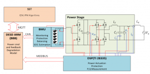
The AC DESD implementation, shown in the figure makes use of the standardized DESD communication and control platform. At the lowest level, a TI TMS320F28335 digital signal processor (DSP) implements control loops for the power electronics, which actuate the real and reactive power commands from the DGI. The DSP communicates via the MODBUS protocol to the local Beagle Bone Black ARM Board, which links to the FREEDM distributed grid intelligence (DGI) via the MQTT protocol. The DSP receives power and relay status commands from the DGI via the ARM Board and reports the actuated power and relay status. The Toshiba battery modules have an integrated battery management system (BMS). The BMS measures the battery voltage, current, temperature; estimates the battery state-of-charge (SOC); and communicates this information to the local ARM board using CAN communication. The BMS monitors all five LTO battery modules, and autonomously controls two additional relays if a fault condition is detected (overvoltage, overcurrent, temperature rise, or leakage current). The ARM board collects the information from the battery and the DSP and uses this information to implement higher-level applications, such as calculating round trip efficiencies, and running the on-line battery degradation model.
Considering all the factors involved in having an efficient energy storage device installed wherever required, the desired functionality of FREEDM DESDs are as shown:
- Physical System Interfaces
Multiple DC and AC DESDs are connected to a single SST.
| Parameter | Value |
| Capacity: | DC DESD module is rated at 1kW/1kWh. The input voltage (battery side) for a single module is 12Vdc (10-16V) nominal and the output voltage is 360-400Vdc nominal. AC DESD module is rated at 5kW/5kWh. The output voltage is 120Vac. For the modular DESD design, the input (battery) voltage is rated at 48V nominal (42V minimum), and the system contains 4 modules (each module delivers 1.25kW/1.25kWh). |
| Battery Specification: | Batteries rated at 1C operation. |
| Temperature R: | Operating temperature: -10 to 500C Storage temperature: -20 to 700C |
| Self-Discharge Rate: | Not more than x |
| System Power Density | |
| System Energy Density | |
| Minimum/Target System Round Trip Efficiency: | 90%/95% |
- Control/Measurement/Diagnostic Interfaces
| Parameter | Value |
| Control Inputs: | P command (power – W), Q command (reactive power – VA) works at 1 sec (Sent from Server or ARM board) Plug and Play Status(1 sec) Fault Management Signaling (10 cycles) Droop response to Vdc or frequency (1/2 cycle) |
| Slew Rate: | 0 to rated power actuated in 1/2 cycle |
| Feedback: | P,Q delivered; 1 sec Power (W) and Energy (Wh) available; 1 sec |
| Constraints: | Power (W) and Energy (Wh) available; sample rate -- when pinged |
- Communications/Data Interface
| Parameter | Value |
| AIN |
|
| AOUT |
|
| BIN |
|
| BOUT |
|
- Device Function
These Functions will be a mix of FREEDM-Specific functions (such as IEM, IFM support, or Plug and play) and Traditional grid support functions (such as load following or time shifting…)
Traditional DESD Functions:
| Parameter | Value |
| Electric Energy Time Shift | When the DESD Electric Energy Time shift API is enabled, the battery will be charged when the price signal is below a threshold and will be discharged when the price signal exceeds a threshold, which the safe operating region of battery parameters (i.e. temp, voltage, current and state of charge) |
| Load Following | |
| Renewable Firming |
FREEDM DESD Functions:
| Parameter | Value |
| Droop Control | When the main grid is off or when the power being supplied is not enough for all the loads, droop control strategy is implemented to share the load in the best possible way. This procedure is explained in Use Case 7 |
| Plug and play | |
| Fault Management | |
| Black Restart | Energy storage device provides the reference voltage and frequency for the DER that we choose to be the black-start power supply |
| Power management funct’s | The power management module in DESD should take care of generating the current command for DC grid depending on the requirement and limits. This is explained in Use Case 7 |
| Energy management funct’s | The energy management module in DESD should be able to estimate the SOC of each DESD and generate the P* command as explained in Use Case 7 |

