
- UC1: Plug and Play Functionality
- SST in Islanded mode
- FREEDM system in grid connected mode
- FREEDM system in grid islanded mode
- UC8: IFM for FREEDM system
- FREEDM system in Emergency mode
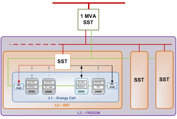
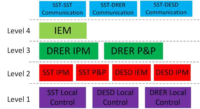
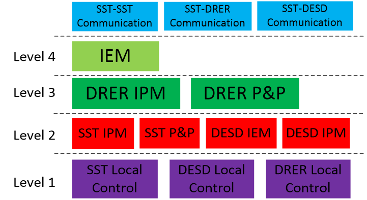
A use case is a valuable tool that is commonly used in software development and systems engineering to identify, clarify, and organize system requirements and interactions. The FREEDM Use Cases, describe how the functions of Plug & Play (PAP), Intelligent Energy Management, Intelligent Power Management and Intelligent Fault Management operate under different operating conditions called scenarios. These Use Cases are controlled by Actors: the people, devices, and systems that interact with the Use Cases. Eight use cases are identified, with several different scenarios within each.
UC1: Plug and Play (P&P) Functionality
There are several requirements for the Plug and play function: 1) it should work automatically without affecting the system operation and stability as soon as the module is plugged into the system; 2) whenever the module is unplugged from the system, the module can stop operating but the microgrid should still work well; 3) when the module is re-plugged into the system, the system has to recognize the module, for example, this module is the DESD or DRER.
To achieve this, the functionalities of various devices in the system, during the plug and play operation are defined below:
- SST grouping management
- Decide closure of FID
- Search attached SST
- Set the DRER working mode based on grid mode and local grid voltage
(A) Operating Strategy:
| # | Step | Actor |
| 1 | SST IPM collects local information from the SST and DESDs of that SST node |
|
| 2 | Calculate the available energy storage of the SST node based on the information from its attached DESDs and send it to the other SST nodes |
|
| 3 | Determine the operating mode of the SST node and send the corresponding commands to the attached SST and DESDs |
|
| 4 | SST IPM waits for the response of SST local controller and attached DESDs, sends a confirmation message to the other SST nodes after receiving the response from the SST and DESDs. |
|
| 5 | SST local controller starts to control the SST with the given operating mode and control references and sends a confirmation message to the SST IPM |
|
| 6 | DESD local controller starts to control the SST with the given operating mode and control references and sends a confirmation message to the DESD IPM |
|
(B) Communications:
- Communication in SST
# Source Recipient Physical Protocol Contents Timing 1 SST controller board SST ARM board PC 104 connector Modbus - P,Q measured from SST 7.2 kV AC grid
- 7.2 kV AC grid voltage
- 7.2 kV AC grid frequency
- High voltage DC link voltage
- Low voltage DC link voltage
- P injected from DC terminal
- P,Q absorbed by SST 120/240 V AC load
- SST operating mode confirmation
0.2 s max 2 SST ARM board SST controller board PC 104 connector Modbus - SST operation mode setting
- Q injection command to 7.2kV AC grid
- Load shedding command
0.2 s max - Communication in DESD
# Source Recipient Physical Protocol Contents Timing 1 DESD controller board DESD ARM board Zigbee Module Modbus - P injected from DESD terminal
- Voltage measured at DESD terminal
- Battery terminal voltage
- DESD operation mode confirmation
0.2 s max 2 DESD ARM board DESD controller board Zigbee Module Modbus - DESD operation mode setting
- P injection command
0.2 s max - Communication in DRER
# Source Recipient Physical Protocol Contents Timing 1 DRER controller board DRER ARM board Zigbee Module Modbus - P injected from DRER terminal
- DC or AC grid voltage
- AC grid frequency (AC only)
- DRER potential power
0.2 s max 2 DRER ARM board DRER controller board Zigbee Module Modbus - P injection command
0.2 s max
FREEDM System in Grid connected mode:
When the system is grid connected, it behaves as follows. The figures shown below explains the behavior of the FREEDM system when it is in grid connected mode. Various modes of operation of the system when in grid connected mode are described in terms of use-cases.

(A) Operating Strategy:
| # | Step | Actor |
| 1 | SST collects local information from other SST cells | |
| 2 | IEM calculated the P command of the DESD and DRER in this SST cell | |
| 3 | SST sends commands or operation limits to the attached devices | |
| 4 | SST controls the AC and DC electrical quantities at its terminals, provides reactive power support at the grid side terminal | |
| 5 | DRERs generate power based on MPPT and limits received from SST | |
| 6 | DESD IEM calculated the P command for each DESD | |
| 7 | DESDs charge or discharge the battery based on the command from DESD IEM |
(B) Control topologies:
- SST Local control
- Regulate grid side power factor (0.01s)
- Regulate high voltage DC-link voltage
- Regulate low voltage DC link voltage (0.001s)
- Regulate 120/240 V grid voltage (0.001s)
- DRER Local control
- Regulate local electrical quantities
- DESD Local control
- Regulate current output of the DESD
(C) Communications:
- SST-SST communication
# Source Recipient Physical Protocol Contents Timing 1 SST1 ARM board SST2 ARM board FREEDM Network DNP3 - P,Q injected to 7.2 kV grid by SST1
- SST1 operation mode
- SST1 DESD overall SoC
- SST1 total load P
- SST1 DG power potential
0.8 s max 2 SST2 ARM board SST1 ARM board FREEDM Network DNP3 - P,Q injected to 7.2 kV grid by SST2
- SST2 operation mode
- SST2 DESD overall state of charge
- SST2 total load P
- SST2 DG power potential
0.8 s max - SST-DESD communication
# Source Recipient Physical Protocol Contents Timing 1 SST ARM board DESD ARM board SST LAN MQTT - P command for DESD power injection
- DESD operation mode command
0.8 s max 2 DESD ARM board SST ARM board SST LAN MQTT - P injected by DESD
- State of charge
- DESD operation mode confirmation
0.8 s max - SST-DRER communication
# Source Recipient Physical Protocol Contents Timing 1 SST ARM board DRER ARM board SST LAN MQTT - P limit command for DRER
- Q command for DRER (AC only)
0.8 s max 2 DRER ARM board SST ARM board SST LAN MQTT - P injected by DRER
- DC or AC grid voltage
- AC grid frequency (AC only)
- DRER potential power
0.8 s max
(D) Function-based operation sequence:

UC4: IEM when FREEDM system is Grid connected
This is the normal and ideal operation of the system. When the FREEDM microgrid is connected to the grid, it is assumed that the voltage and frequency are being regulated.
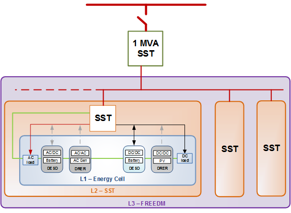
The Intelligent Energy Management (IEM) subsystem is comprised of both hardware and software for intelligent energy management. The hardware component of each IEM node is a Solid State Transformer (SST). Each SST behaves like an energy router, interfacing various loads, DRERs and DESDs in a plug-and-play fashion. In addition to voltage regulation, the SST also controls the amount of active and reactive power into and out of each IEM subsystem. Thus, here the goals of the Intelligent Energy Management system would be:
- Unit commitment
- Incremental cost estimation using ICC algorithm
- Decide whether a particular SST is a leader or a follower
- Shed load according to the requirement and availability
- To estimate SoC of each DESD and to figure out the DESD with maximum SoC
- And to calculate P* (reference P) based on optimization
UC5: IPM when FREEDM system is Grid connected
Intelligent Power Management (IPM) is a combination of hardware and software that optimizes the distribution and use of electrical power in computer systems and data centers.
The goals of IPM when the FREEDM system is in grid-connected mode are:
- Volt/VAR control generates Q*
- Set AC current reference for the commanded reactive power
- Limit the current magnitude
- MPPT for all the DERs.
- Adjust power output according to terminal voltage (LVRT, Power curtail)
- Provide reactive power support (AC DRER)
FREEDM system in grid islanded mode:
When the main grid fails to regulate the voltage and frequency at the substation within the required range, the recloser at the substation will open and the FREEDM system will start operating under islanded mode. The control target with the highest priority under this mode is the voltage and frequency regulation of system. It can only be achieved by changing the operating mechanism of some of the smart devices in the system. The proposed control strategy here is a master-slave control where one of the SSTs plays as the role of regulating the system frequency while the rest of the SSTs operate as current source mode which is very similar with that under the grid connected mode. The SST reactive power control will remain under islanded mode to support the system voltage. The power injections of DESDs are determined by IEM and the master SST to ensure the system stability and reduce overall system operating cost.
Various strategies to be implemeted during the islanded mode operation are discussed below in detail. A master-slave control topology is proposed to achieve the required characteristics during the islanded mode operation.
(A) Operating Strategy:
| # | Step | Actor |
| 1 | SST collects information from the local devices and other SST cells | |
| 2 | Calculate the available energy storage of the SST node based on the information from its attached DESDs and send it to the other SST nodes | |
| 3 | Determine the operating mode (master or slave) of the SST cell and send the corresponding commands to the attached devices | |
| 4 | IEM calculate the P command of the DESD and DRER in slave SST cells | |
| 5 | SST controls the AC and DC electrical quantities at its terminals
|
|
| 6 | DESD IEM determines the P command for each DESD | |
| 7 | DESD operates based on the operating mode and reference values from DESD IEM
|
|
| 8 | DRERs generate power based on MPPT and limits received from SST |
(B) Control topologies:
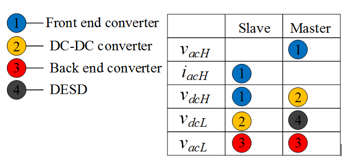
- SST Local Control The control targets of each stage of the SST are determined based on the operation mode generated by the SST IPM. Table shown below, gives a comparison of the electrical quantities controlled by each stage under master mode and slave mode.
 Control algorithm goals:
- Master SST
- Regulate high voltage DC-link voltage
- Regulate AC grid voltage (0.001s)
- Regulate 120/240 V grid voltage (0.001s)
- Slave SST
- Regulate grid side power factor (0.01s)
- Regulate high voltage DC-link voltage
- Regulate low voltage DC link voltage (0.001s)
- Regulate 120/240 V grid voltage (0.001s)
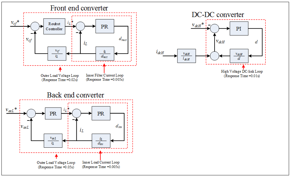
Under slave mode, the back end converter controls the voltage at low voltage ac terminal; the DC-DC converter regulates the low voltage dc-link voltage; the front end converter controls the high voltage dc-link voltage. In addition, the front end converter has to control the ac side current in order to balance the dc-link voltage. It also has the capability to support the system voltage by injecting reactive current component. Fig. gives an example of the structure of the SST local control under slave mode.
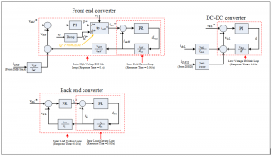 Under master mode, the front end converter regulates the ac terminal voltage (frequency and magnitude). The high voltage dc-link voltage is regulated by the DC-DC converter, and the low voltage dc-link voltage regulation is left to the attached DESDs. Fig. gives an example of the structure of the SST local control under master mode.
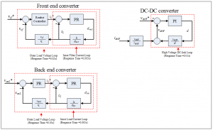
- Master SST
- DESD Local Control
- Regulate current output of the DESD
- Regulate DC grid voltage (master DESD in master SST cell)
- DRER Local control
- Regulate local electrical quantities

(C) Communications:
| SST ARM | DESD ARM | DRER ARM | |
| SST controller board | PC 104 connector (Modbus) | N/A | N/A |
| DESD controller board | N/A | Zigbee module (Modbus) | N/A |
| DRER controller board | N/A | N/A | Zigbee module (Modbus) |
| App/Enterprise | SST | DESD | DRER | |
| App/Enterprise | DNP3 | N/A | N/A | N/A |
| SST | N/A | TCP/IP | SST LAN (MQTT) | SST LAN (MQTT) |
| DESD | N/A | SST LAN (MQTT) | N/A | N/A |
| DRER | N/A | SST LAN (MQTT) | N/A | N/A |
- Communication in Master SST:
- SST controller goal
- Regulates the 7.2 kV AC grid voltage
- Regulates the 12 kV DC link voltage
- Regulates the 400 V DC link voltage
- Regulates the 120/240 V AC grid voltage
- SST ARM goal
- Communicates between SST-SST, SST-DESD, and SST-DRER and collects system information
- Optimizes the power flow based on power market (Set active power and reactive power for slave SSTs)
- Select master DESD in group based on their state of charge
- Regroups the SSTs (define the master or slave)
# Source Recipient Physical Protocol Contents Timing 1 SST controller board SST ARM board PC 104 connector Modbus - P,Q measured from SST 7.2 kV AC grid
- 7.2 kV AC grid voltage
- 7.2 kV AC grid frequency
- High voltage DC link voltage
- Low voltage DC link voltage
- P injected from DC terminal
- P,Q absorbed by SST 120/240 V AC load
- SST operating mode confirmation
0.2 s max 2 SST ARM board SST controller board PC 104 connector Modbus - SST operation mode setting
- 7.2 kV grid voltage magnitude and frequency
- Load shedding command
0.2 s max
- SST controller goal
- Communication in Master DESD:
- DESD controller goal:
- Regulates the DC micro-grid voltage
- DESD ARM goal:
- Receives the master command from the group SST ARM board
- Estimates the state of charge
- Sends the information of power injection and state of charge back to SST ARM board
- Group DESD into SST (plug and play)
# Source Recipient Physical Protocol Contents Timing 1 DESD controller board DESD ARM board Zigbee Module Modbus - P injected from DESD terminal
- Voltage measured at DESD terminal
- Battery terminal voltage
- DESD operation mode confirmation
0.2 s max 2 DESD ARM board DESD controller board Zigbee Module Modbus - DESD operation mode setting
- DESD terminal voltage command
0.2 s max
- DESD controller goal:
- Communication in DRER:
- DRER Controller goal:
- Regulates the resource generation power by adjusting PV terminal voltage or wind turbine torque
- Regulates the DC or AC terminal current to DC or AC grid
- DRER ARM goal:
- Receives power curtail command from SST ARM
- Sends power command to the controller board
- Group DRER into SST (plug and play)
# Source Recipient Physical Protocol Contents Timing 1 DRER controller board DRER ARM board Zigbee Module Modbus - P injected from DRER terminal
- Voltage measured at DRER terminal
- DRER potential power
0.2 s max 2 DRER ARM board DRER controller board Zigbee Module Modbus - P injection command
0.2 s max
- DRER Controller goal:
- SST-SST communication:
- Goal:
- Collects the battery state of charge information in other SST groups
- Collects load information of the other SSTs
- Collects available DG information in other SST groups
# Source Recipient Physical Protocol Contents Timing 1 SST1 ARM board SST2 ARM board FREEDM Network DNP3 - P,Q injected to 7.2 kV grid by SST1
- SST1 operation mode
- SST1 DESD overall state of charge
- SST1 total load P
- SST1 DG power potential
- Power sharing scaling factor
0.8 s max 2 SST2 ARM board SST1 ARM board FREEDM Network DNP3 - P,Q injected to 7.2 kV grid by SST2
- SST2 operation mode
- SST2 DESD overall state of charge
- SST2 total load P
- SST2 DG power potential
0.8 s max
- Goal:
- SST-DESD communication:
- Goal:
- Collects local battery state of charge information
# Source Recipient Physical Protocol Contents Timing 1 SST ARM board DESD ARM board SST LAN MQTT - DC voltage regulation command
- DESD operation mode command
0.8 s max 2 DESD ARM board SST ARM board SST LAN MQTT - P injected by DESD
- State of charge
- DESD operation mode confirmation
0.8 s max
- Collects local battery state of charge information
- Goal:
- SST-DRER communication:
- Goal:
- Collects local available DG information
# Source Recipient Physical Protocol Contents Timing 1 SST ARM board DRER ARM board SST LAN MQTT - P limit command for DRER
- Q command for DRER (AC only)
0.8 s max 2 DRER ARM board SST ARM board SST LAN MQTT - P injected by DRER
- DC or AC grid voltage magnitude
- AC grid frequency (AC only)
- DRER potential power
0.8 s max
- Collects local available DG information
- Goal:
UC6: IEM when FREEDM system is Islanded
The job of the IEM algorithm implemented for the FREEDM system in islanded mode is as follows:
- Unit commitment
- Incremental cost estimation using ICC algorithm
- Decide whether the SST being master or slave
- Load shedding
- Estimate SoC (decide DESD with the max SoC)
- Calculate P* based on optimization
- Decide master DESD (in master SST cell)
UC7: IPM when FREEDM system is Islanded
- Master SST
- Generate frequency/voltage reference
- Balance power without overloading master SST
- Slave SST
- Volt/VAR control generates Q*
- Set AC current reference for the commanded reactive power
- Limit the current magnitude
- Generate current command to the DC grid for the power command following
- Limit the power output
The key characteristics that can be achieved from the SST IPM algorithm design are as follows:
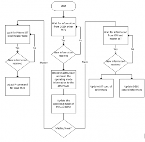
- The operating mode of SST and DESDs (master or slave) at the SST node is determined by the SST IPM
The proposed strategy is based on evaluating the amount of available energy storage of every SST node. SST IPM will gather the information from attached DESDs and send the total number of the energy storages that SST node to the other SSTs in the system. Based on the ranking of available energy storage of the SST nodes, the SST node with the highest one will be picked as the master SST while the others will operate as slave mode. Once the operating mode has been determined, the SST IPM will send a confirmation of its operating mode to the other SSTs to avoid the confliction between more than one master SSTs. A different SST node will automatically become the new master when its amount of energy storage becomes higher than the existing master SST node. This can be achieved by dynamically sharing the amount of energy storages among all of the SSTs in the system. - The operating modes and reference values needed for the SST and DESD local controls are generated in SST IPM. The SST and DESDs will switch the operation mode or adjust control reference values when new commands are received from the SST IPM.SST IPM needs to monitor status of the attached devices including the outputs and internal electrical parameters of the SST and DESDs.
Ideally, the master SST will compensate the mismatch between loads and power generations in the system no matter how large the mismatch is. However, the master SST has its limit on absorbing or injecting real power which means the slave SSTs should adapt their real power injection or absorption when the master SST doesn’t have enough capability to compensate mismatch between loads and generations in the system. Under master mode, the SST IPM keeps monitoring the real power injection at the SST high voltage ac terminal and adapts the real power commands for the slave SSTs in the system following a designated algorithm. Under slave mode, the SST IPM needs to keep updating the power command for the DESDs based on the received commands from IEM and the master SST.
- MPPT for all the DERs
- Adjust power output according to terminal voltage (LVRT, Power curtail)
- Provide reactive power support (AC DRER)
FREEDM system in Emergency mode
Emergency mode operation is activated when any of the communication between various devices might be lost.
| # | Step | Actor |
| 1 | SST collects information from local devices |
|
| 2 | Calculate the available energy within the SST cell, determine whether the SST cell is source or load. Send the operating mode to attached devices |
|
| 3 | SST controls the AC and DC electrical quantities at its terminals
|
|
| 4 | DESD IEM determines the P command for each DESD |
|
| 5 | DESD operates based on the operating mode and reference values from DESD IEM
|
|
| 6 | DRERs generate power based on MPPT and limits received from SST |
|
The individual responsibilities of each component in the system are described as follows
- Solid State Transformer:
- IEM:
- Load shedding
- Estimate SST cell energy
- SST P&P:
- Check for communication availability
- Control FID for grid connection status change
- Control FID for load shedding
- SST IPM:
- Source SST
- Generate 7.2 kV grid side voltage reference based on droop characteristic
- Load SST
- Control the grid side power factor
- Limit the current magnitude
- Source SST
- SST Local control
- Source SST
- Regulate high voltage DC-link voltage
- Regulate AC grid voltage (0.001s)
- Load SST
- Regulate 120/240 V grid voltage (0.001s)
- Regulate grid side power factor (0.01s)
- Regulate high voltage DC-link voltage
- Regulate low voltage DC link voltage (0.001s)
- Regulate 120/240 V grid voltage (0.001s)
- Source SST
- IEM:
- Distributed Renewable Energy Resources (DRER)
- DRER P&P
- Search attached SST
- Set the DRER working mode based on grid mode and local Vgrid
- DRER Local control
- Regulate local electrical quantities
- DRER IPM
- MPPT
- Adjust power output according to terminal voltage (LVRT, Power curtail)
- Provide reactive power support (AC DRER)
- DRER P&P
- Distributed Energy Storage Devices (DESD)
- DESD IEM
- Estimate SoC (decide DESD with the max SoC)
- Calculate P* based on optimization
- Decide master DESD (in source SST cell)
- DESD IPM
- Generate current command to the DC grid for the power command following
- Limit the power output
- DESD Local control
- Regulate current output of the DESD
- Regulate DC grid voltage (master DESD in source SST)
- DESD IEM