
Solid-state transformer (SST) is a collection of high-powered semiconductor components, conventional high-frequency transformers and control circuitry which is used to provide a high level of flexible control to power distribution networks. Add some communication capability and the entire package is often referred to as a smart transformer.
SST technology can step up or step down AC voltage levels just like that of the traditional transformer but it also offers several significant advantages. These include:
- allow two way power flow
- input or output AC or DC power
- actively change power characteristics such as voltage and frequency levels
- improve power quality (reactive power compensation and harmonic filtering)
- provide efficient routing of electricity based on communication between utility provider, end user site and other transformers in the network
- greatly reduce the physical size and weight of individual transformer packages with equivalent power ratings
When SSTs are implemented, they will radically change the way utility power is distributed. They will also become integral components in the future Smart Grid - enabling it to direct power from any source to any destination by the most efficient route possible.
In this section, we will see the defined system functionality of the Solid State Transformer first and the proposed system configuration with various levels of control for the designed system to meet the desired functionality in the later parts of the section.
(A) Desired SST functionality
- Control/Measurement/Diagnostic Interfaces
| Parameter | Value |
| Control Inputs: | High V AC port: P, Q command (1 sec) Low V AC port: V, f, P, Q command (1 sec) Plug and Play Status(1 sec) Fault Management Signaling (10 cycles) |
| Command Slew Rate: | 0 to rated power actuated in 1/2 cycle |
| Feedback: | High V AC: iACH, vACH (12 kHz) High V DC: VDCH (12 kHz) Low V DC : VDCL (12 kHz) Low V AC : iACL, vACL (20 kHz) |
| Constraints: | Power (W) and Energy (Wh) available; Voltage (V) and Current (A) ratings of devices; |
2. Communications/ Data Interface
| Parameter | Value |
| AOUT |
|
| AIN |
|
| BOUT |
|
| BIN |
|
3. Device Function-FREEDM SST Functions:
These Functions will be a mix of FREEDM-Specific functions (such as IEM, IFM support, or Plug and play) and Traditional grid support functions (such as load following or time shifting…)
| Parameter | Value |
| DC Droop Control |
|
| Plug and play |
|
| Intelligent Fault Management |
|
| Black Restart |
|
| Intelligent Power Management Functions |
|
| Intelligent Energy Management Functions |
|
(B) FREEDM System Configuration
Fig. 1 shows the SST-based system configuration proposed and implemented in Future Renewable Electrical Energy Delivery and Management (FREEDM) Systems Center at North Carolina State University. This system can operate in SST-enabled mode or islanding mode. SST is adopted to replace the conventional low-frequency transformer and rectifier/ inverter because of its better controllability.
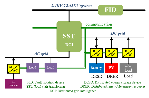 Fig.1 FREEDM System configuration
SST Hardware Testbed
Table below, gives the specifications of the designed SST system. The typical test setup is SST delivering power from the 3.6 kV AC port to 120 V AC port and 200 V DC port. The power rating for low voltage DC grid is 4 kW and AC grid is set to 6 kVA.
SST Specifications:
| Parameter | Value |
| Capacity: | Total SST VA Rating: 10 kVA |
| Port Specification: | High V AC port: 3.6 kV, -2.78 A ~ 2.78 A Low V AC port: 120 V, -83.3 A ~ 83.3 A Low V DC port: 200 V, -50 A ~ 50 A |
| Temperature Range: | Operating temperature: -10 to 50oC Storage temperature: -20 to 70oC |
| Self-Discharge Rate: | N/A |
| Minimum System Level Round Trip Efficiency: | 95% |
The topology of SST is represented in Fig. 1, where a rectifier stage is connected to a dual half bridge (DHB) converter through the 6 kV DC link. The secondary side of the DHB is connected to the inverter through the 200 V DC link. The fault isolation device (FID) is connected in series with the rectifier side inductor. FID is made of two ETOs which regulate the inrush current by controlling the fire angle during the start up. When fault occurs, both ETOs are turned off. The high voltage side switches use 13 kV SiC MOSFET. The hardware is shown in the figure shown below.
 Fig. 2 SST topology
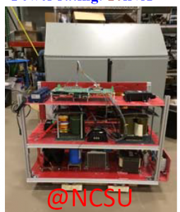
Fig. 3: SST Hardware model built at NCSU
Distributed Grid Intelligence Design
An intelligent control platform with communication functions is needed for the SST in the smart grid environment. This unit is called the distributed grid intelligence (DGI) in the FREEDM system. The DGI hardware has been designed for the SST in the smart grid environment.
Fig .x shows the signal flow path of the presented DGI platform. Basically, the command will be generated by the central control room and transmitted to the ARM board by wireless communication. Then, this command will be delivered to the local DSP+FPGA control board, in which the switching sequence of the SST is generated. Further, the interface board sends the PWM signal optically to the SST. In the reversed signal path, the status of the SST is fed back to the central control room for monitoring and control.
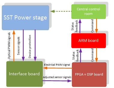
Fig .4 Universal controller signal flow path
There are total three signal boards for fulfill the SST control as shown in Fig. 5. The first board is the universal control platform. This board is a signal adapter board. It measures the voltage and current quantities on the power hardware and it sends out optical isolated PWM pulses to the actual power switches. Also, it is a power supply for the other controller boards by taking small amount of power from power hardware.
The next board fulfills the local control algorithms. The local controller board has one TI TMS28335 DSP and two Xilinx Spartan XC3S400 FPGAs as shown in Fig. 3. It takes the measured signal from universal control platform and digitalizes the analog signals by A/D chips. The digitized signals are sent to the first FPGA. DSP takes the sampled signals from the first FPGA and calculates the next cycle PWM pulses. Then DSP sends PWM pulses or duty cycle to the second FPGA. Without fault, the second FPGA passes the PWM pulses or generates PWM pules and sends the PWM pulses to the universal control platform.
The last board is for communication. The communication between SSTs is achieved by using the ARM board TS-7800, which features Marvell 500MHz ARM9 SBC, providing gigabit Ethernet. Both wire/wireless communications can be realized. The command received by the ARM board is sent to the first FPGA on local FPGA+DSP board. And the local information sent to ARM board for communication is sent from the first FPGA through PC104 protocol.
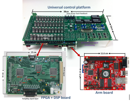 Fig .4 Universal control platform for SST prototype
System Control Strategy
Distributed control strategy should be embedded into the local controller for system reliable operation in case that the communication ports fail. The control strategy is needed to ensure proper and optimal operations of the system under different operation modes. Some major challenges for SST-enabled system include:
- to manage individual module in system based on their different characteristics when system in SST-enabled mode;
- to seamlessly switch system from SST-enabled mode to islanding mode;
- to make the system reliable in islanding mode;
- to extend the battery life-time.
One example of system-level control strategy combining the centralized and distributed control for DC bus voltage is shown in Fig. 6.
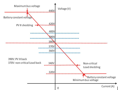 (a) Operation curve for DC bus voltage
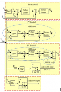 (b) Control blocks
Fig. 6 Control strategy for FREEDM DC bus voltage
From the control strategy shown in Fig. 6, DC Droop control functionality can be achieved.